


Experiments with electronics
Modifications to the Gaussmeter
Battery Powered
In order to power the Gaussmeter from a battery, a power supply similar to the one shown below will work quite well. It uses two 9v batteries, connected in series, with the common coming from between them. This is needed to make a bipolar supply. Off of the +9v side is a 5v regulator, to create the +5v needed by the Hall Effect device. The op amps are now supplied with the +9v and -9v instead of the +15v and -15v as shown on the previous schematic. Everything else works the same way. However, please realize that the op amps can only output a voltage which is within 2v of the supply voltages. This means that with +9v and -9v supplying the op amps now, the maximum output voltages are about +7v (corresponding to 700 Gauss North) and -7v (corresponding to 700 Gauss South). By reducing the gain, though, you can have 1000 Gauss give you 5.00v out. Just remember to mentally multiply the output voltage V1 by 200 instead of 100 to give you the correct Gauss reading.
LED Indicators for North and South Poles
If you'd like to have a Red LED indicate a North magnetic pole and a Green LED indicate a South magnetic pole, here is a circuit that can be added onto the previous schematic. It simply is an op amp (using one of the op amps in the quad 324 package not used in the basic Hall Effect circuit) acting as a comparator. Whenever the output voltage V1 is positive, meaning a North pole, the Red LED turns on. Whenever the output voltage V1 is negative, meaning a South pole, the Greed LED turns on. There is a little hysteresis built in so that the LED will remain in the last state until a larger opposite signal from V1 comes along. The Yellow LED simply is on whenever the power supply is on.
Analog Meter Output
For some applications, it is better to use an analog meter to get a better feeling for how the strength of a magnetic varies. It provides a more visual indication, rather than reading numbers off of a digital meter. For this to work properly, though, we need an absolute value circuit since most analog meters can only indicate positive voltages. The circuit below does the job pretty well. The 11v zener on the output across the meter connections is to prevent the needle of the meter from being pegged if the voltage goes over 10v. The input to this circuit is again the output V1 of the previous schematic.
Hand-Held Battery Powered Gaussmeter and Parts List
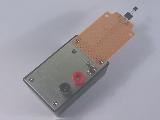
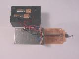
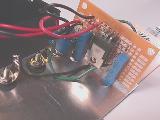
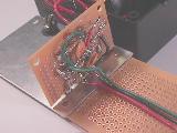
Here is a list of parts used for the basic Gaussmeter and the battery supply described above to make the hand-held Gaussmeter shown in the photos.
Description |
Qty |
Radio Shack P/N |
Approximate Cost, each |
| 9v Battery | 2 | 8.99/4 | |
| Battery Clips | 2 | 270-325 | 1.39/5 |
| 7805 Voltage Regulator | 1 | 276-1770A | 1.49 |
| 324 Quad Op Amp | 1 | 276-1711 | 1.29 |
| 0.1uF Cap | 2 | 272-135 | 0.69/2 |
| 10K, 15 turn Pot | 2 |
271-343 | 1.49 |
| Plastic Box | 1 | 270-283A | 3.99 |
| DPDT Switch | 1 | 275-663B | 3.59 |
| Socket for the Hall Effect | 1 | 276-1988 | 1.39/3 |
| Perf circuit board | 1 | 276-150A | 1.19 |
| Terminal Posts for meter | 2 | 274-661A | 2.59/4 |
| Wire, 22AWG solid | 1 | 278-1221 | 4.49/3 rolls of 90' each |
| Resistors, 1/4w | 1 | 271-312 | 7.99 for 500 piece assortment |
| Hall Effect Device | 1 | (see text) | 10.00 |
You may want to first make sure everything works correctly using a breadboard, such as the one from Radio Shack, P/N 276-169. It costs about $21.99, but can be used over and over for all of your new projects as well. The bundle of resistors listed above gives you a nice selection of 5% resistors to work with. If you have trouble finding any of the items, take a copy of this page and the previous schematic to a Radio Shack store and they could certainly help find the parts. The DPDT switch in the list is what I used for the DPST switch shown on the schematic for the battery supply. The second 0.1uF cap in the list was placed across the op amp terminals 4 and 11. The socket was cut so that only the three leads from the Hall Effect Device could plug in. You may want to add a 14 pin socket for the 324 op amp IC. The box I put this into is quite crowded (it's only 3-3/16 x 2-1/8 x 1-3/8"), so you may want to use a slightly bigger one. The terminals are used to plug a digital voltmeter into this to read the output voltage from V1. Radio Shack does have a little voltmeter LCD display, P/N RSU 11461498, for about $19 which might work, but I haven't tried it.