

Experiments with electronics
Build your own Gaussmeter ![]()
A slightly more expensive Gaussmeter ![]()
This Gaussmeter can use the same Hall effect device as the one above, but what I used was a device from a different company, (a device not recommended by the manufacturer for new designs any longer since availability is not guaranteed, but they only cost $0.89 each!), with a different sensitivity: 1.3mV/G. However, the major differences between this Gaussmeter and the one above, is that this unit will give you a positive voltage out for North poles, negative voltages out for South poles, and will read 8.00Vdc for 800Gauss (North pole), and will read -5.43Vdc for 543Gauss (South pole). In a modification described, I also added a couple of LEDs to give me a visual indication of North or South pole. There is also a circuit added so it can work with an analog meter (which only measures positive voltages). The circuitry is a little more complex, but not much. It can operate off of batteries or you can build a power supply for it.
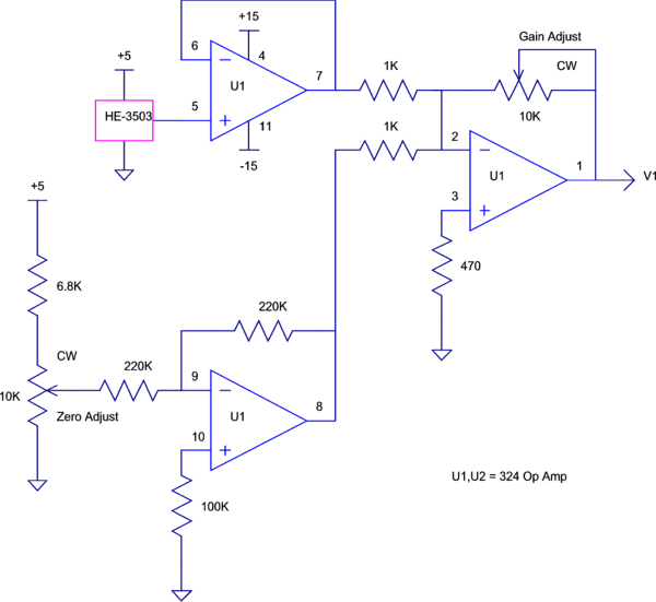
The schematic for this is below, along with some construction details.

The key to the Gaussmeter is the magnetic field sensor, labeled HE3503 in the schematic above. I obtained a calibrated, analog output Hall Effect device made by Cherry Electrical Products (1-800-285-0773, in Waukegan, Illinois) but is no longer available from them. Their model number was HE503. Allegro MicroSystems (508-853-5000, in Worchester, Mass) has a very similar product, model number UGN3503. Check out their web sites to see what specs you may be interested in. The HE503 came with a calibration report which stated what the output of the device was at various Vcc voltages (ranging from 4.5 to 6.0Vdc) and from -1000 to 1000 Gauss. Radio Shack sells a calibrated Hall device as P/N RSU 12033684, for about $60. It contains only the Hall device, an Allegro A3516LUA, and nothing more except for data sheets. You would still have to build the rest of the circuit as described here if you want something useful.
For an updated discussion on where to obtain a Hall Effect Device, visit this supplies page.
It is a three lead device, where one lead is for Vcc, one is for common, and the third is the output. For example, at Vcc = 5.000Vdc, and with 0 (zero) magnetic flux, the output is 2.530Vdc (about half of the Vcc voltage). At -1000 Gauss (north pole), the output drops to 1.409Vdc. At +1000 Gauss (south pole), the output rises to 3.651Vdc. (This is saying that its sensitivity is 1.121mV/G) Its non-linearity is only 0.2% and its symmetry is about 99.8%! It even has a flat response to 23kHz. This is a great device and costs only about $10! (The calibration report gives you the exact numbers for your particular device).
The next thing you need is a power supply which can provide +5.00Vdc at 10ma, +15Vdc at 20mA and -15Vdc at 20mA. By the way, a +12 and -12Vdc supply could be substituted for the +15Vdc and -15Vdc supply. (Check this for a battery powered meter) I had a handy little power supply from Datel, their triple output model, which can supply +5.00Vdc at 500mA, +15Vdc at 200mA and -15Vdc at 200mA, all with 120Vac in. They have more efficient units available today, but this worked great. If you don't have something like this, you may need to pick up a booklet which tells you how to build one using a transformer and three voltage regulators along with a diode bridge and filter caps. The Hall Effect device draws 9mA typically.
The +5.00Vdc is for the Hall Effect device and the Zero Adjustment pot circuit only. The +15Vdc is connected to the op amp + supply, (U1 pin 4), and the -15Vdc is connected to the op amp - supply, (U1 pin 11).
The op amp I used was a 324 quad, but a TL084 would actually work better. (Two TL082s would also work. Just be sure the - inputs and the + inputs and the outputs of the individual op amps are connected as shown, disregarding the pin numbers.) To properly finish things off, connect U1 pin 12 to common and connect U1 pin 13 to U1 pin 14.
How does the rest of the circuit work?
The circuit for the Hall Effect device is not hard to understand. I soldered the Hall Effect device to a four conductor phone cable (using only 3 of the 4 conductors) and put heat shrink tubing over the device and its leads to protect it. This allows me to be able to move it around easily. The other end of the cable is connected to +5.00Vdc, common, and an op amp, U1 pin 5, as a buffer (so the output of the Hall Effect device is not affected by the load connected to it). The output of the buffer, U1 pin 7, is connected to a 1K resistor to the inverting input of another op amp, U1 pin 2.
In parallel with this, is the Zero Adjustment circuit. This is made up of a 10K pot (I used a 15 turn pot for easy adjustment) in series with a 6.8K resistor across the +5.00Vcc to common. This allows the output of the pot enough of a range to equal the output of the Hall Effect device at 0 Gauss. The wiper of the pot goes to an inverting op amp, U1 pin 9. The output of the inverting op amp, U1 pin 8, is connected to a 1K resistor to the inverting input of U1 pin 2. (This is the same input to which the output of the buffer op amp is connected to). The purpose of this Zero Adjustment circuit is to subtract 2.530Vdc from the Hall Effect device, so that when there is 0 Gauss present, the output of the Gaussmeter is 0Vdc.
The output of op amp U1 pin 1 amplifies the Hall Effect signal from the buffer, subtracts the Zero Adjustment voltage from it, inverts it, and amplifies the result. The output is a voltage, V1, which is positive for north magnetic poles, and negative for south magnetic poles. Its magnitude is set by the Gain Adjustment so that 1000 Gauss causes 10.00Vdc to appear on the output. The Gain Adjustment is a 15 turn 10K pot, providing a range of gain from 0 to 10. It will be set to a gain of about 8.92.
I then connect a digital voltmeter between V1 and common and simply read the polarity and magnitude of the magnetic field wherever the Hall Effect device is placed.
Here is how I calibrate the Gaussmeter.
1. Turn the Gain Adjustment fully clockwise to get maximum gain.
2. Making certain the Hall Effect device is not close to any magnets, adjust the Zero Adjustment pot to obtain 0.00Vdc out. It may end up at +0.01 or -0.02, but that's pretty close and may be acceptable.
3. Unplug the Hall Effect device from U1 pin 5 and connect the wiper of another 10K pot to that pin. The clockwise end of the pot is connected to +5.00Vcc, and the counter-clockwise end is connected to common. Using the calibration chart which came with the device to determine what the output voltage of the device would be with a 1000 Gauss field, set the pot to give that voltage on its wiper. On mine, this corresponded to 1.409Vdc.
4. Set the Gain Adjustment pot to obtain +10.00Vdc out.
5. Remove the 10K pot from U1 pin 5 and replace the Hall Effect device output to it.
It is now set to measure the magnetic fields of magnets and electromagnets. Its output will be a positive voltage for a north magnetic pole, a negative voltage for a south magnetic pole, and 1.00Vdc will correspond to 100 Gauss. If the output were connected to a scope, you would also be able to see the varying magnetic field of an AC electromagnet!
Here is a table of magnetic fields and expected output
voltages at various points in the circuit:
(Using the actual voltages for the device I have noted above. U1-5
means U1 pin 5)
| Magnetic Field | U1-5 | U1-7 | U1-8 | U1-1 |
| 1000 Gauss North | +1.409 | +1.409 | -2.530 | +10.00 |
| 500 Gauss North | +1.970 | +1.970 | -2.530 | +5.00 |
| 0 Gauss | +2.530 | +2.530 | -2.530 | 0.00 |
| 100 Gauss South | +2.642 | +2.642 | -2.530 | -1.00 |
| 1000 Gauss South | +3.651 | +3.651 | -2.530 | -10.00 |
If you have any questions or difficulty, please let me know.
For other modifications to this circuit, check here.
