


Experiments with magnetic levitation
Suspended Objects
There's a super article in Popular Electronics, May 1996, pp 48-52, 78, titled "Build a Magnetic Ball Levitator", by James Cicon. It describes how to build an electromagnet with an optical sensor which will keep a hollow steel ball floating in the air about 1/4" below the electromagnet.
This is like the globe of the earth which is suspended in air under an electromagnet that can be purchased for about $125. The material costs for this project is only about $20.
A copy of the article should be obtainable from your local public library.
A place on the net with something like this can be found at:
http://www.aussiemagnets.com.au/millennium.html (a new item, looks great!)
http://www.arttec.net/Levitation/Kit.html (see photos and write-up below)
Some other sites on this are:
http://www.dimi.uniud.it/~franco/SysDynLab.html
http://www.brucegray.com (cool magnetic sculptures)
Another way to suspend an object is by using a solenoid. Check this page on solenoids.
Still another method is to use
diamagnetics. http://www.scitoys.com/scitoys/scitoys/magnets/suspension.html
Zero-Gravity Levitator
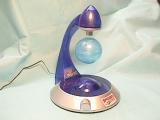
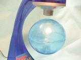
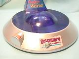
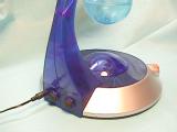
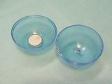
This is a super toy! Very new (at least for me)!
It is from www.unusualdevices.com for Discovery World, and costs about
$50. It stands just over 11" high, the globe is 3" in diameter,
and comes with is power supply which plugs into the 120Vac wall outlet. On
the back is where you plug in the power supply, there is also an on/off switch
and a switch which turns on the rotating function. This will cause the
globe to rotate at a rate of about once every 3 seconds. This is
accomplished in a very clever way: in the base are two coils,
perpendicular to each other, which has a NIB magnet on edge in their
middle. When the rotating function is on, the coils cause the magnet to
rotate, which in turn affects the NIB magnet which is located in the bottom of
the globe, on its edge, causing the globe to rotate. On the front left of
the base is an orange knob which can be rotated, adjusting the distance between
the top of the globe and the bottom of the electromagnet (which is contained in
the top, pointed part of the toy). There is a large NIB magnet in
the top of the globe. I works very well. The globe comes
apart, and an additional 1.5 ounces can be placed in the globe. More
than that will cause it not to float. The only drawback is that when power
is interrupted or the unit is turned off, the globe falls and hits the
base. One of these times, it will break. I may need to place
some padding under the globe, formed to catch and hold it if and when it falls.
(seems like www.unusualdevices.com disappeared! Try getting it from Edmund
30825-32)
Levitation Kit
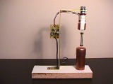
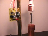
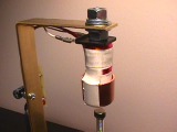
This kit was purchased on line from http://www.arttec.net/Levitation/Kit.html where it comes in a few levels of assembly (you solder the parts onto the printed circuit board, or you buy a ready made unit complete with power supply, or something between). The ready made kit came with the electromagnet wound onto the bolt and a hall effect device taped to the end of the bolt for sensing the magnet that is being levitated, both are wired to the small printed circuit board that has the PWM and controls, and the power supply that plugs into the wall outlet and supplies 15Vdc to the circuit board. Two magnets, each about 3/8" diameter by 3/16" thick, were included. This was designed and sold by Guy Marsden. He also provides a very nice instruction sheet describing how it works and how to make it work. If you go to his site given above, you can get a copy of an article he did on this circuit. He did a very nice job with very few parts.
What I did was to purchase a 3/4" wide, 12" long and ~1/16" thick brass bar. I bent it into the "Z" shape you see, drilled holes into it to hold the electromagnet, to mount the control board, and fasten it to the wooden base. The base is particle board with a white melamine surface, usually used for shelves. I wanted the LM18201 IC that is on the control board to be fastened to the brass bar to help keep it cool. I could have used an aluminum bar instead, but this brass one was readily available at ACE hardware. After I mounted the electromagnet and the control board, I shortened the white wires that went to the electromagnet. It made the assembly a little neater. I used fast-on clips instead of soldering the wires to the electromagnet's terminals.
When I started playing with it, I noticed (and was told in other articles) that the control for the magnet was kind of unstable. I tried several different weights of items to have hanging in the air, but they all started to wiggle up and down or back and forth, getting more and more wild, before it finally either fell to the floor or stuck to the bolt. Since the hall effect device is on the bottom of the bolt, I was concerned that the magnet would smash it and damage it. To help with that, I did the following:
First, I carefully took the wires from the hall effect device (brown, red, orange wires on my unit) and smoothed them along the side of the electromagnet. I then taped them to the electromagnet near the top. Then I purchased a 3/4" copper pipe cap from the hardware store. It is shaped like a small cup. I slipped it up over the bottom of the electromagnet. To hold it in place, I taped it straight down one side of the electromagnet, under the bottom, then back up. I also took some tape and put it around the top of the electromagnet to cover the top ends of the piece of tape. Since copper affects the magnetic field only a small amount, it allows the field to penetrate it, but keeps the magnet from smashing directly into the hall effect device or sticking to the bolt with a lot of force - making it difficult to remove. OK, one problem solved.
Next, I tried a lot of simple things to create a stably levitating object. I ended up with a bolt that is about 1-3/8" long (including the flat head), 1/4-20 thread, and super-glued a magnet onto each end of this bolt. I set up the polarities so that either end can be up and float under the electromagnet. It only weighs about 0.4oz (11g), with both magnets. More than that and it has difficulty suspending it. I don't know how others get heavier stuff to float.
The biggest problem was to make it stop oscillating up and down and eventually falling or sticking to the bolt. Guy had suggested using a copper plate to help dampen the oscillations. I got a piece of 1" copper pipe, slipped an end cap onto it, and placed it under the floating bolt. I made the height of the copper damper to be about 1/4" below the bottom magnet. Actually, you can do some fine tuning by simply sliding the end cap up or down a little. With this in place, the unit works OK. It can sit there for hours and not overheat, not oscillate and fall apart, but just look cool!
Fix for the Levitator
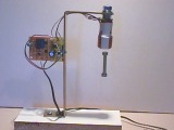
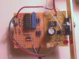
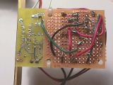
However, a better (and cooler) way to make the levitating object stable is to add a feed-forward term to the circuit. This is explained very well in an article by Kumpf.
I modified the circuit in order to use components that could be purchased from Radio Shack and could still use the same power supply! I used a trick to obtain a negative voltage supply. I put all of the components onto a small perf board, as seen above, and wired it to the original board. Here is the schematic:

Here is a description of what is needed. Carefully remove the wire that is the output from the Hall Effect Sensor (HES) from the circuit board. This will be taken to the new circuit at Vin, which is on pin 3 of the quad op-amp IC. What this circuit is doing is providing a feed-forward signal to counteract the oscillations, damping them out and providing stable operation.
Wire up the new circuit as shown. The output at Vout, which is on pin 14 of the quad op-amp IC, connects to the original circuit board where the output from the HES used to be. Watch the polarity of the 10uF cap. The - end goes to pin 7 of the op amp, and the + end goes to pin 10 of the op amp.
The power supply needs to be modified as follows:
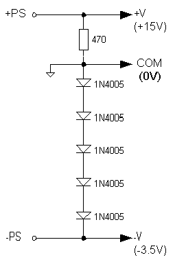
Remove the -PS wire, from the power supply, from the original circuit board. Connect this to the point labeled -PS on the modified supply circuit shown in the schematic above. This will also be the -V connection to the op-amp. The point in the supply circuit that is labeled COM would go to everything in the new circuit that has the "common" symbol on it. This common also feeds to the original circuit board where the -PS wire used to be (labeled GND). The +V in the circuit comes from the +PS on the original board and feeds the +V of the op-amp.
What this modified power supply is doing is creating a negative supply without extra transformers and other stuff. There is a 0.7V drop across each diode. This creates a -3.5V at the -V point with respect to COM. The +V will be about +15V with respect to COM. This means that you would measure about 18.5V from -PS to +PS, from the power supply. All that is needed for the op-amp is a small negative voltage to make it work, and this gives it just what it needs.
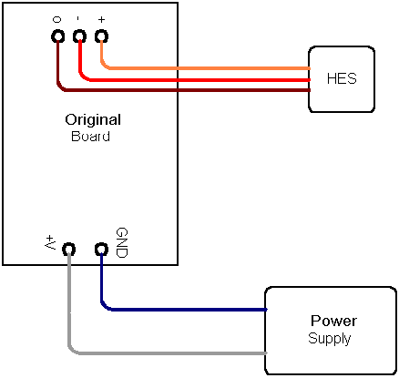
Above is the original hook-up between the original circuit board, the power supply and the Hall Effect Sensor (HES). Not shown are the two wires going from the Original Board to the electromagnet. Those are not disturbed.
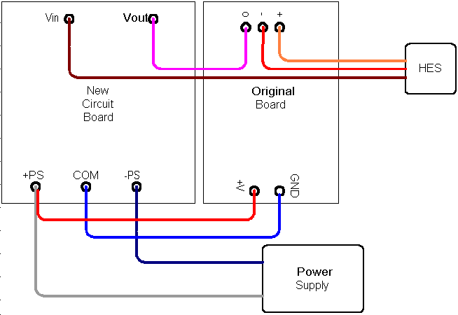
This shows the new circuit board and the connections between it and the power supply and the HES.
Typical voltages, when working, are as follows:
V at op-amp pin 1 = +0.7V
V at op-amp pin 7 = -1.0V
V at op-amp pin 8 = -0.07V
V at op-amp pin 14 = +1.0V
You will need to adjust the 10-turn pot so that the magnet assembly will be about 0.25 to 0.38" below the electromagnet. It will be very stable and can stay there for days and days.
A parts list for your trip to Radio Shack:
1 LM324 quad op amp
P/N 276-1711 $1.49
1 14 pin
socket
P/N 276-1999 $1.29 for 2
1 10K Ohm, 10 or 15 turn
pot P/N
271-0343 $2.59
1 Dual PC
board
P/N 276-148 $1.79 (used
only half of it)
1 10uF, 35V
cap
P/N 276-1025 or -1013 $0.99
1 1K Ohm
resistor
P/N 271-1321 $0.99 for 5
2 10K Ohm
resistor
P/N 271-1335 $0.99 for 5
1 100K Ohm
resistor P/N
271-1347 $0.99 for 5
1 470 Ohm resistor, 1/2W P/N
271-1115 $0.99 for 5
5 1N4003 or 1N4005 Diode P/N
276-1653 $0.69 each
Total cost is only about $16. If you have some parts at
home laying around, it would cost less.
To make your own magnetic levitator from scratch, go to the next page!