


Experiments with motors
DC Motors ![]()
DC motors are fairly simple to understand. They are also simple to make and only require a battery or dc supply to make them run.
Here is a great site that describes how DC motors work.
http://www.howstuffworks.com/motor.htm
There are several types of basic DC motors you can build.
They make super science fair projects.
http://store.intellaliftparts.com/Electric_Motor.html
(a simple dc motor using one battery)
http://www.hb.quik.com/~norm/motor/
http://simplemotor.com/
(a very clever design of a dc motor with a permanent magnet armature)
https://store.qkits.com/
http://store.jalts.com/elmogekit.html
Check out the SDK200 kit for $24. Looks like a nicely packaged kit.
A DC Motor ![]()
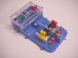
Here is a photo of a kit we put together. It works very well, and is a great demonstrator of a DC motor or a DC generator. There are several types of these kits available as noted above, as well as some very simple ones. Edmund 36-273 about $13
A Simple DC Motor ![]()
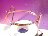
This is my version of what others call the "World's Simplest Motor". It consists of 7.5 turns of #26 AWG magnet wire, wound onto a large Excedrin bottle, a D cell battery holder, and a couple of pieces of household wiring wires. The magnet is one of the large donuts that is available from several sources. Scrape the insulation off of the straight ends of the magnet wire where they touch the black and the white insulated wire, but only on one side of the wire's diameter. Check the links above for details. With 1.5V on it, it spins at about 800RPM! To see my version of the world's simplest AC motor, check this out!
Maxwell's Motor ![]()
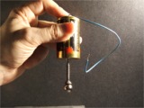
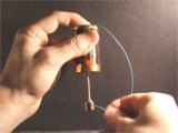
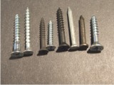
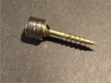
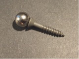
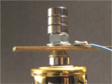
This simple motor is a lot of fun to put together, and it takes so few parts to make it. This was first brought to my attention by Ed Pegg Jr, who described this on his MAA web site. He shows Gary Foshee holding Maxwell's Motor, causing the magnet and screw to spin. All you need is a battery, a pointed screw, a cylindrical or spherical magnet, and a wire. That's it! Stick the screw onto one end of the magnet as shown. Then, stick the pointed end of the screw onto the + terminal of the battery. I used that terminal so it does not travel around as much as it would on the - terminal, but either will work. Hold one end of the wire to the - terminal, and touch the other end of the wire to the side of the magnet. The magnet and screw will start spinning. With the parts I used, the current that is drawn from the battery is 5.8 Amps, and this will cause the magnetic rotor to spin at over 2000rpm! Wow! (I used a digital strobe to check the speed.)
Let's talk engineering. The magnet does not need to be a single cylinder. I actually used two disk magnets that are stuck together. If the magnet(s) is too heavy, the screw will not stick to the battery and will fall off. If the screw is too long, the screw will not stick to the battery. If the point on the screw is too blunt, it will stick to the battery, but will not spin very well and will wobble and slow down quickly. The third photo shows the different types of screws and nails I tried. I ended up with the following: D cell battery, two NIB magnets - each 0.5" diameter and 0.2" thick or a single 0.375" diameter spherical magnet, a Phillips flat-head steel deck screw that is 1.25" long with a sharp point on it (don't use a coated screw since that will not conduct electricity, nor an aluminum screw that will not stick to the magnet), and a 6" piece of #20 AWG stranded wire that I had around. The wire can be most any size. Stranded will work best. A C cell or AA cell battery should work too, but I wanted something with the ability to source more current. The spherical magnet is nice to use because it centers itself onto the Phillips head of the screw, and is well balanced. You only need to touch the wire to the side of the magnet for one or two seconds. It will then be spinning real fast, and will take about 60sec for it to stop spinning. The reason for the point on the screw is to create a very low friction bearing.
How does it work, and is it possible to predict what direction it will spin in? I thought this was a simple example of the left hand rule for motors. Instead, it follows an anti-left hand rule concerning the force on a current carrying wire in a magnetic field. You will notice as you play with this that it will not work if you touch the loose end of the wire to the screw. Nor will it work if you touch the wire to the middle of the bottom of the magnet. You have to touch the wire to the outside surface of the magnet. As the current flows from the + terminal of the battery, down through the screw, into the magnet, and out the side of the magnet into the wire and on to the - terminal, something is taking place. The current is flowing across the magnetic field within the magnet. This magnetic field is flowing from the South pole to the North pole within the magnet. So, using the left hand rule, the first finger points in the direction of the field. If the North end of the magnet is on the head of the pointed screw, then this finger has to point up. The second finger points in the direction of the current flow. It would be from the center of the magnet to the outside surface of the magnet where the wire touches it. The thumb now points in the direction where a force is acting on the current flowing through the magnet. However, since the exit location of the current is fixed, so the current can not move, the force is against the mass of the magnet in the opposite direction. That force will cause the magnet to spin counter-clockwise (CCW) when viewed from above.
If you were flip the magnet over, it will spin in the clockwise (CW) direction. If you were to flip the battery over, it would spin in the CW direction. If you did both of these things, it would spin in the CCW direction again. Cool!
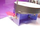
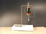
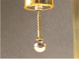
I then made a fixture to mount it. I used a brass strip, bent it into a "Z" shape. In the top I placed a short, 1/4-20 flat head steel screw so a magnet would stick to it. It is held in place with a washer and nut. There are three more magnets sitting on top of the nut as you can see. A magnet is stuck to the head of the screw. The battery is stuck to the magnet. Nice way to hold a battery. The wire is attached to a ring lug and placed under the nut holding the 1/4-20 screw. Then, put the pointed screw with the spherical magnet onto the + terminal and you are set to wow your friends and neighbors.
Check out: http://en.wikipedia.org/wiki/Homopolar_motor
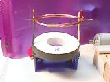
Homopolar Motor ![]()
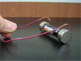
I received the photo above and a video (591KB avi) (761KB wmv) from Sean Stewart who came up with the idea of placing two magnets onto a AA battery, so that the same pole is stuck to each end of the battery, and touch a wire to the sides of the two magnets, similar to the Maxell's Motor. Then, let the motor roll itself along - really, really cool! The magnets need to be a little bigger than the diameter of the battery, like 5/8" or 3/4" in diameter for a AA battery, and about 1/4" to 3/8" thick. Download the video to see this motor in action. Sean calls it the Simple Rolling Homopolar Motor. He improved upon a similar motor design described in "The Physics Teacher" by Sugimoto and Kawada. I'm still working on my version.
A Brushless DC Motor Kit ![]()
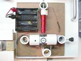
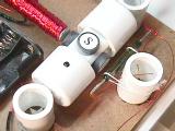
This kit is from http://simplemotor.com/. He did a great job of coming up with the idea and putting it together. This one uses the reed switch. He now has a couple more designs using hall effect devices and transistors - again very well done. The kit was easy to assemble, and works great. With 1.5V on it, it spins at about 1500RPM! (I used a calibrated strobe to measure that).
Brushless DC Motor
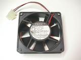
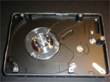
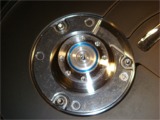
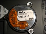
Most computers use brushless DC motors since they are clean (no brushes to create carbon dust or to wear out) and are now smaller and less expensive than even shaded pole AC motors. In reality, inside the hub of the motor are three sets of windings and a set of permanent magnets with sensors. As the magnets on the hub rotate past the sensors, the windings are turned on as needed to produce the torque needed. With 12V on it, it spins at about 2800 rpm. Check http://www.ebmpapst.us/en/ . The other three photos are of the motor from a hard drive as found in a computer. Nicely machined especially since it will be spinning at 5400 rpm!
Industrial DC Motors
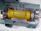
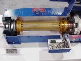
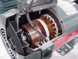
These are cut-aways of actual DC motors, showing the field windings, commutator and the armature. You will notice that the armature laminations are skewed slightly in order to reduce the torque ripple that would normally be present. These are manufactured by Reliance Electric, part of Baldor Motors.
Cell Phone Vibrator Motor
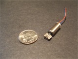
This is a photo of a tiny DC motor that you might find in your cell phone or your pager. It is used to create the vibration when the phone is in "vibrate" mode. As you can see, the offset weight connected to the motor shaft causes the vibrations when the motor spins. I'll bet you didn't know that you were carrying a motor around with you, did you? Next time you have the opportunity, take an old cell phone or pager apart and locate the motor in it.