

Experiments with magnets and our surroundings
Designing Magnetic Circuits
Designing circuits with magnetic fields is very similar to designing electrical circuits.
With simple electrical circuits, we use an EMF (voltage
source) and resistors, and can determine how much current will flow.
Similarly, for magnetic circuits, we use an MMF and reluctance of materials, and
can determine how much flux will flow.
See Magnetic Fundamentals.
Here are links to help you learn about magnet circuit designs, and can provide you with details and examples.
http://www.magnetsales.com/
http://www.magnetsales.com/Magnet_Design.htm
http://www.magnetsales.com/Design/DesignG.htm
http://www.magnetsales.com/Design/Glossary.htm
http://www.dextermag.com/
http://www.dextermag.com/resource-center/document-library
http://www.usneodymiummagnets.com/
http://www.usneodymiummagnets.com/calculator.html
Check out all the sections they have on design guidelines.
This is a great tutorial, as all of the above sites are.
Raggio's Electromagnet Design Cookbook
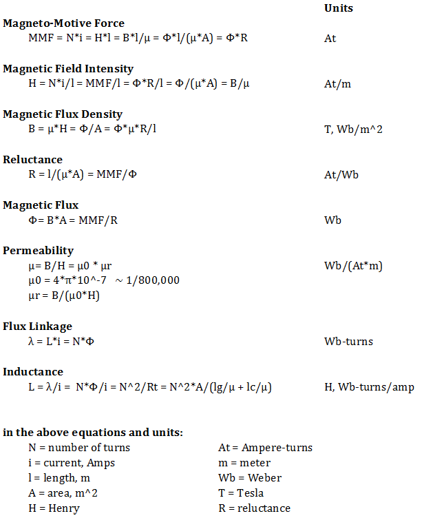
Magnetic Identities
Below are various identities for these magnetic terms, and
their units.
Use whichever one has the information you know.

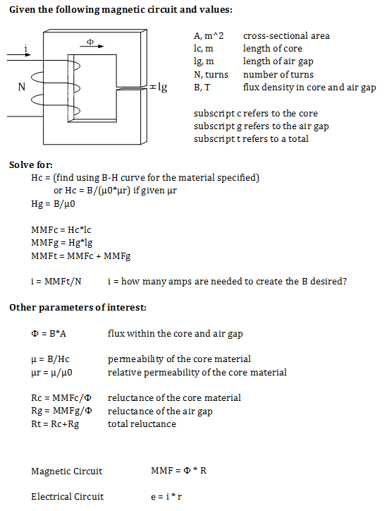
A Typical Problem
Often, you need to create a circuit that will produce a
certain amount of flux within an air gap.
This problem below can be used as a first pass.

A Solved Example:
Let
A = 1 cm x 3 cm = 3*10-4 m2
lc = 60 cm = 0.6 m
lg = 1 mm = 1*10-3 m
N = 500 turns
B = 1.1 T
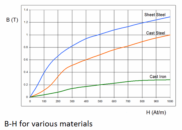
We will be using sheet steel for the core material, so we will need the B-H
curve for this material.

From the chart, we can find that for this particular type of steel:
Hc = 600 At/m when B = 1.1 T
Hg = B/µ0 = 0.9 / 4*pi*10-7 = 716.2*103 At/m
MMFc = Hc*lc = 600 * 0.6 = 360 At
MMFg = Hg*lg = 716.2*103 * 1*10-3 = 716.2 At
MMFt = 1076.2 At
i = MMFt / N = 1076.2 / 500 = 2.15 A
So, with 2.15A flowing into the 500 turns of winding, with this particular type of steel, you would see something close to 1.1 T within the air gap.
If the circuit actually had two air gaps, simply add the two together and model it with one, larger air gap. One thing that does also happen is that within the air gap, the flux tends to spread out a bit into the air, filling a slightly larger area. So, the solution isn't exact, but is close, since we didn't take this fringing into account.
A larger air gap
What would happen if the air gap were made twice as large, but
we still wanted 1.1 T within the air gap?
lg = 2 mm = 2*10-3 m
Hc is the same
Hg is the same
MMFc is the same
MMFg would be twice as large = 1432.4 At
MMFt = 1792.4 At
i = 1792.4 / 500 = 3.58 A
The current would have to be 167% larger in order to create the same flux density of 1.1 T within the larger air gap!
A smaller air gap
What would happen if the air gap were made half as large, but
we still wanted 1.1 T within the air gap?
lg = 0.5 mm = 5*10-4 m
Hc is the same
Hg is the same
MMFc is the same
MMFg would be half as large = 358.1 At
MMFt = 718.1 At
i = 718.1 / 500 = 1.44 A
The current would only have to be 67% of the original current
in order to create the same flux density of 1.1 T within the smaller air gap!
Lesson Learned
The air gap has the bigger effect on how much current (and MMF)
is needed in order to create some kind of flux density within an air gap.
Every motor and generator has to have air gaps between the rotor and the stator
in order to allow the rotor to rotate without rubbing against the stator.
However, the smaller the air gap, the lower the current for the same flux
density.