


Experiments with magnetic levitation
Home-Built Magnetic Levitator ![]()
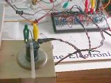
With this assembly, I was able to suspend a magnet about 1" below an electromagnet. Here are the details on the circuit design.
This project requires you to have some familiarity with building and testing electronic circuits. A great way to start is to obtain an "Engineer's Mini-Notebook" book from Radio Shack, by Forrest M. Mims III, on building circuits. He has a lot of different booklets out for all sorts of projects. They go into a fair amount of detail so you'll start to learn how the circuits work, how to put things together, etc. Or, if you have a friend, teacher, or know someone who is an electrical engineer, electrical technician, sound technician, etc, ask him/her for some guidance, and I'm certain they would be glad to help lend a hand.
Suppose we would like to design a device that would allow us to suspend an
object a fixed distance below an electromagnet as shown here. How can we do
this? First, let's review the theory behind a controller that we will need.
Feedback Regulation
If the electromagnet used to suspend the object were simply operated with a
fixed amount of current, this would not be able to maintain any kind of control
over the position of the object. If the object were too close to the
electromagnet, it would be pulled right up to it. If it were too far away from
the electromagnet, it would fall to the floor. There would be no way to adjust
for or compensate for the slight variations that take place in order to maintain
the object at a fixed distance from the electromagnet. This would be called an
"open loop" control system.
We need the ability to quickly control the current to the electromagnet depending upon the position of the object to the electromagnet. This will allow us to be able to suspend the object under the electromagnet at a fixed distance. This kind of improvement is only possible when the control for the electromagnet can monitor the position of the object and regulate the current to the electromagnet. For example, when the object gets too close to the electromagnet, the current in the electromagnet will decrease, allowing the object to begin to fall away due to gravity. When the objects gets too far away from the electromagnet, the current in the electromagnet will increase, pulling the object closer to the electromagnet. Basically, it will do whatever is needed with the current in the electromagnet in order to keep the object at a fixed distance below the electromagnet. This is called a "closed loop" or "feedback" control system.
The heart of the closed loop system is the regulator or feedback controller.
This can be simplified to a set of inputs and outputs connected as shown here.
The goal of this system is to make the process output equal to the reference
input at all times, even if the process is perturbed by outside forces. We will
describe each of the components of this system and relate them to a familiar
control system: the speed control operation of a car by a driver.
1). The input signal is called a Reference Input or command. In our example,
this would be the speed limit sign stating that the limit is 55MPH.
2). The Feedback signal is a representation of the process output of the system,
and is used for comparison to the reference. Most often the feedback signal goes
through a converter or amplifier so its signal can be directly compared to the
reference input signal. In our example, the feedback signal is obtained from the
speedometer stating that the car is traveling at 45MPH.
3). The Comparator simply subtracts the feedback signal from the input signal in
order to create an Error or difference signal. A positive error signal will
cause the process output to increase. Similarly, a negative error signal will
cause the process output to decrease. In our example, the comparator is a mental
operation where the driver determines that the speed limit is 10MPH over his
present speed. Since the error signal is positive, the driver will press harder
on the gas pedal.
4). The Error Amplifier converts the error signal to something the process can
use. The type and gain of this amplifier directly affects how quickly and how
well the output of the process will follow the reference input. In our example,
the amplifier is the engine of the car. The position of the gas pedal controls
the amount of fuel going to the carburetor, which controls the torque produced
by the engine.
5). The Process or load takes the output from the amplifier and converts it to
the Process Output which is the parameter being monitored and controlled. Even
if the output from the error amplifier does not change, the process can vary
over time which will affect the output of the system. This is where the beauty
of a feedback control system shines. Since the feedback signal continually
monitors the process output, and is continually being compared to the reference
input, the system can continually adjust for variations in the process.
In our example, increasing the torque out of the engine causes the speed of the car to increase. When 55MPH is achieved (process output equals the reference input), the drives lets up on the gas pedal which reduces the engine torque in order to maintain this speed. However, as he begins to climb a hill, the car will slow down even though the engine's torque (amplifier output) has not changed. The speedometer (feedback) will indicate the reduction in car speed, the comparator (driver) will calculate a new error signal and will increase the amount of fuel going to the engine. The engine (error amplifier) will produce more torque causing the speed of the car to again increase. As the crest of the hill is reached, the car will begin to speed up and exceed the speed limit. The driver will again adjust by letting up on the gas pedal. However, if there is a malfunction in the control system such that the comparator (driver) does not respond to the over-speed condition, flashing red lights accompanied by a loud siren will appear in the rear view mirror. This will command a new reference input of 0MPH causing the control system to bring the car to a stop!
This example can be summarized as shown here.
Basic Methods
For our project, we need to do something similar. The feedback system for
this is going to be basically the same.
The Reference Input is now the Position Input or command.
The Comparator compares the Position Input to the position Feedback.
The Error Amplifier amplifies the difference between the Position Input and the
Feedback.
The Amplifier Output is the current going to the electromagnet.
The Process being controlled is the strength of the electromagnetic field.
The Process Output is the position of the suspended object with respect to the
electromagnet.
The Feedback Amplifier is some kind of device or system used to detect how far
away the object is from the electromagnet.
Now, all we have to do is design the circuitry needed for perform each function within each box above. How do we do this? First, we need to decide what we are going to suspend and how we are going to detect the distance of the object from the electromagnet. There are several methods open to us. Let's look at a few of them and select one.
Here we show a steel ball as the suspended object, with an energized
electromagnet providing the force to counterbalance gravity.
Now, how do we detect the distance between the electromagnet and the ball?
Looking at the diagrams, we can use an infrared light emitter and detector set
up so that the ball will block only a certain portion of the light. If the
infrared is totally blocked, the ball is too close. If the infrared isn't
blocked at all, the ball is too far away. If just half of the infrared is
blocked, the position of the ball is just right.
Another method would be to again use an infrared light emitter and detector, but
aimed to reflect off of the surface of the ball. Again, if no infrared bounces
back, the ball is too far away. If too much infrared bounces back, it is too
close. If there is just the right amount of infrared, the position of the ball
is just right.
There is also available an ultrasonic emitter and detector, used in some cameras
to do the automatic focusing. If this were placed under the ball, the strength
of the signal would tell us how far away the ball is located. The circuit would
be set to command a specific distance. I don't know how fast these devices can
respond to changes in distance.
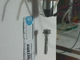
Instead of using a steel ball, what if we were to use a permanent magnet for the
suspended object? What options are open for us for doing the detection? One
thing we may want to do with the magnet is to stick a small steel bolt to it in
order to make it a little more stable so it wouldn't flip over easily.
Again, we could use any one of the methods already mentioned with the steel
ball. They are shown here.
However, we could also do a couple of other things. If the object could contain
two magnets, one could be used with the electromagnet for the suspension, and
the other could be placed at the bottom of the object, close to where we would
place a hall effect device. This device could be used to indicate how close the
bottom magnet is, so we would know how far away the object is from the
electromagnet. The object would have to be a stiff item, not spongy.
Another method would be to use two hall effect devices, one mounted onto each
end of the electromagnet. When no permanent magnet is near, no matter how much
current is in the electromagnet, the two hall effect devices' signals would
cancel each other out. When a magnet gets closer to one, then the difference
between the two signals starts to increase. So, it is this difference in signals
that we could monitor and control. (By the way, this idea was patented in US
patent number 4,910,633. Because of this, you would be infringing on the patent
holder's rights to produce and sell something like this. However, there is no
problem making something like it for your own use, you just can not sell it.)
Let's do that. We'll use two, linear hall effect devices to monitor the magnetic field at each end of the electromagnet. When the permanent magnet gets too close to one, their difference signal will increase. When the permanent magnet gets too far away, their difference signal will decrease to zero.
The Control Circuit
The feedback amplifier will need to take two, linear hall effect device
signals and subtract one from the other to give us a difference signal. This
difference signal will be compared to our position reference signal, and the
error will be used to control the amount of current in the electromagnet. The
first part of the circuitry is shown here.
This is the heart of the feedback circuitry. The linear hall effect device,
HE3503, is fed from a +5V source. Now, when there is no magnetic field near the
hall effect device, its output voltage is about 2.5V. When a North pole
approaches the marked surface of the device, the voltage drops to about 1V at
1000 Gauss. When a South pole approaches it, the voltage rises to about 4V at
1000 Gauss. What we want to do is make the output at V1 equal to zero when there
is no magnetic field, +9V at maximum Gauss North pole, and -9V at maximum Gauss
South pole. To do this, we will use LM324 op-amp ICs that contain four op-amps
(TL084 also works well). First, we take the output of the hall effect device
directly into an op-amp, OA1, that acts like a follower (its output is the same
as the input, but with lower impedance). It then feeds a 1k resistor into
another op-amp, OA3, that acts like an amplifier with an adjustable gain between
0 and 10 times. In order to get rid of the 2.5V offset when no magnetic field is
present, we have the ZERO_1 pot that feeds from the same +5V supply, and is
inverted by OA2.
To set this up, we start with no magnetic field near the hall effect device. Set the GAIN_1 fully clockwise for maximum gain, and look at the voltage test point V1. Adjust ZERO_1 until the voltage at V1 is zero. Now, place the hall effect device onto the electromagnet. When full power is applied to the electromagnet, adjust GAIN_1 to get +9V out at V1.
Next, we build another circuit identical to this one, and label the pots
ZERO_2 and GAIN_2. Set them up the same way. Its output is at test point V2.
The way we attach these hall effect devices to the steel core of the electromagnet will have an affect on how the feedback will work. We want the top surfaces of the hall effect devices on the face of the steel core, for both the one on the top and the one on the bottom of the electromagnet core. This is diagramed below when we talk about construction.
The reason for this is to obtain two opposite polarity signals. The gain
adjustment pots will be tweaked to make sure they cancel each other out when no
magnet is near either one of them. This way, V1 will be the negative of V2, and
their sum, V3, will be zero volts. When a magnet approaches one of the ends of
the electromagnet, causing an imbalance in their output signals, the sum of V1
and V2 will no longer cancel and V3 will no longer be zero but could be positive
or negative, depending on the polarity of the magnet.
The output V3 is the position feedback signal. We now need a position reference
signal. This comes from the pot labeled POSITION. The next op-amp compares V3 to
the POSITION pot voltage level, and creates an error signal at test point V4. If
V3 is closer to zero than the POSITION voltage level (please note that the
POSITION voltage level is a negative voltage) the output V4 will integrate to
about +10V. If the absolute value of V3 is greater than the POSITION voltage
level, then the output V4 will integrate to 0V and stay there. The diodes around
that op amp prevent V4 from going negative. This completes the reference input,
feedback amplifier, feedback signal, comparator and error signal portions of the
circuit.
Power Circuit
Now on to the error amplifier, process and the process output sections of
the control.
This circuitry takes the error signal, V4 (from the op-amp in the previous
circuit above), and uses it to control the current in the electromagnet,
directly controlling the strength of the electromagnet's magnetic field. The 555
timer on the left is a free-running oscillator that operates around 1kHz at V6.
Its duty cycle is about 1%. The 555 timer on the right takes that signal and
creates a pulse-width-modulated signal, using the oscillator as the carrier
frequency, and with a duty cycle proportional to the voltage seen at V5. Please
note that the DUTY-CYCLE LIMIT pot sets the maximum duty cycle allowed out at
V7. When V5 gets close to the +V of 12 volts, the PWM becomes erratic, so this
pot prevents this from happening. This also limits the maximum current that the
electromagnet will be allowed to carry by limiting the voltage to the
electromagnet.
V7 feeds the gate to an IGBT (insulated gate bipolar transistor) causing it to turn on when V7 is high, and turn off when V7 is zero. The pulse-width-modulation simply allows the IGBT to be on for a certain portion of its 1kHz cycle, and off for the rest. The average of its on time to its cycle time will be proportional to the average current in the electromagnet. This allows for quick response. The only thing the IGBT can do is turn on or off, it can not reverse the current through the electromagnet if the permanent magnet gets too close and needs to be pushed away. We are counting on gravity to pull the permanent away from the electromagnet when the IGBT is off.
The electromagnet is powered by its own 24V source. It will be handling a fair amount of current. There is a fast recovery diode around the electromagnet to allow the current that was flowing through it to "freewheel" around. If it weren't there, the electromagnet would create a very high voltage whenever the IGBT switched off, damaging the IGBT. The diode around the IGBT isn't needed for this circuit, but is part of the IGBT package.
Construction
For the op-amps, use LM324 or TL084 type ICs. There are four op-amps within
each IC package. For the unused op-amp sections, simply connect them as shown
below.
For the LM555 timers, I suggest using a single LM556 IC package that contains
two timers. For both the timers and the op-amps, follow the signal inputs and
names as shown on the schematics. The diodes used with the op-amps are 1N4148
signal diodes. The pots are all 10k, 10 turn pots, making them easy to adjust.
The resistors are 1/8 watt parts. They can be purchased separately, or you can
get a package with a variety of resistors, which I'm sure you'll want to use
sometime in the future for other projects. You may need to do some tweaking with
this project as well. A parts list of the items from Radio Shack is below.
The power supply needed for this will require +5V, +12V and -12V outputs, all at about 150mA load. I would suggest that you obtain a used computer power supply for this. That should work real well. Or, you can build your own. In the schematic, +V means +12V, and -V means -12V. In addition, we will need a 0 to +24V supply at 10 Amps for the electromagnet. It's good to start with a variac, with a full-wave diode bridge, feeding an electrolytic capacitor. This way, you can have absolute control of the voltage to the electromagnet while you check out the circuit and controls. The diodes used for the bridge were Eupec P/N DD46S12K parts, two diodes per module. The capacitor was rated for 4700uF at 400Vdc.
The three parts that are more difficult are the electromagnet (we can make our own), the IGBT, and the freewheeling diode for the electromagnet.
Let's start with the electromagnet. First, you will need a bobbin (the plastic form that holds the wire) and about 300 feet of #26 AWG magnet wire. (It's called magnet wire because it is used for making electromagnets.) To obtain this, you can purchase 4 packets of magnet wire from Radio Shack. All you will use is the #26 gauge wire, but don't throw the rest away! Start with one of the bobbins with the #26 gauge wire on it (the middle size diameter wire - the others are either thinner or thicker). Don't remove the wire from the first bobbin. It is nicely wound, and we'll start with that. Carefully remove the insulation from about ½" on the ends of the wire. Now, take the other bobbins of #26 gauge wire, and again remove the insulation from their ends. Slide a 1" piece of heat-shrink insulation over the end of the first bobbin's wire end, and then solder that end of wire to the wire end from bobbin number 2. It may be good to twist the bare ends of wire together before soldering, to make sure there is a good mechanical connection. After the solder cools, slide the heat shrink tubing over the soldered joint and shrink it on to insulate the connection. Now, carefully wind the wire from bobbin number 2 onto the first bobbin. When you get to the end of bobbin number 2, you will connect it to the wire from bobbin number 3 and so on until you have all 300 feet (4 * 75 feet) of #26 gauge wire onto bobbin 1.
The iron or steel core was taken from an 8" long bolt, 3/4-13 (diameter in inches and the number of threads per inch). I cut off the hex head of the bolt and cut off the threaded portion of the shaft so that I was left with a smooth, steel cylinder about 5" long and 3/4" in diameter. It should be made shorter so that you would have about 1/4" sticking out of each end of the electromagnet bobbin.
Fasten the hall effect devices to the steel core. Again, have the
marked end of each face the core. (They could also both face the other
way, but have them do the same thing. Don't have one face the core and the
other face away from the core. Otherwise, their signals would not
subtract. Place the hall effect devices as close to the middle of the
3/4" faces of the core as possible. We want them to see the same kind
of flux. To fasten them down, you could use superglue. I used
double-sided tape and a ty-rap to hold them in place. This way, I could
move things around if needed. Also, put a piece of foam rubber over the
bottom hall effect to protect it. When the magnet gets too close to the
core, it will be quickly attracted to the core and could damage the hall effect
device if it weren't protected with the piece of foam.
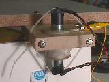
To hold the electromagnet, I cut a hole in a piece of wood, the same size as the winding, and then sliced the wood so I could open it up, place the electromagnet into the hole, and refasten it (kind of like a clamp). The bobbin end prevents the electromagnet from falling out. The steel core was held in place with tape and a ty-rap (plastic cable fastener).
The IGBT I used was rated for 300A and 1200V (way overkill, but was available). It is a Powerex P/N CM300HA-24H. I then used a Semikron SKR60F17 diode for the freewheeling diode around the choke. Another possibility would be to use a Powerex CM200E3Y-12H for the IGBT and it includes a fast recovery diode for the freewheeling diode. Mount the IGBT module and diode to an aluminum plate or heat-sink, and even blow it with a fan in order to keep it cool. The electromagnet, especially, will need to be kept cool. A small fan helps a lot.
Testing
After the items are assembled, you will want to begin to check out each
section. Remove the 1k resistor at V7, remove the 10k resistor at V3, and
connect the end of the DUTY-CYCLE LIMIT pot that was on V4 to +12V.
Let's start with the electromagnet. Start with the electromagnet connected directly across the 24V supply capacitor. Begin by bringing up the DC voltage on the variac, watching the current flowing in the electromagnet. At 10Vdc, you should have about 1 amp flowing. Make sure the winding doesn't get too hot to touch. All OK? Good!
Now, let's set up the hall effect amplifiers. With the power to the electromagnet off, set the ZERO_1 pot fully CCW and the GAIN_1 pot fully CCW. Look at V1. It should be about 2.5V as noted before. Now, begin to turn the ZERO_1 pot CW while monitoring V1. Keep turning until V1 becomes 0.0V (zero volts). As you increase the voltage to the electromagnet, continue to monitor V1. It should stay very close to 0.0V. Now, with the voltage on the electromagnet at about 10V, turn the GAIN_1 pot CW until V1 is at 8.0V.
Repeat this for the other hall effect amplifier while monitoring V2 and adjusting ZERO_2 and GAIN_2. Now, check V3. It should be close to 0.0V when the voltage to the electromagnet is off, and when it is at 10V. If not, adjust GAIN_2 so that it stays close to 0.0V while the voltage on the electromagnet is varied from off to 10V.
Now, check that V6 is creating a 1kHz series of narrow pulses. As you vary the DUTY-CYCLE LIMIT, you should see the pulses at V7 change width. As the voltage increases at V5, the widths increase at V7. You will also find out the maximum voltage that V5 can go to without causing strange jumps in the widths seen at V7. Make note of that. We will call this its max setting.
If this is all working OK, then replace the 1k resistor at V7. The positive voltage pulses will turn on the IGBT, causing current to flow through the electromagnet. With this connected, you should now be able to control the voltage across and the current through the electromagnet simply by adjusting the DUTY-CYCLE LIMIT pot, that control V5. Set it fully CCW. Turn up the variac to 10V. Make sure that with the pot fully CCW, the voltage across the electromagnet is zero. With the pot turned to its max setting, the voltage across the electromagnet should be close to 9 or 10V.
Now, let's do some feedback checking. While checking V3, and with V5 at zero (DUTY-CYCLE LIMIT pot fully CCW), bring a magnet close to the end of the electromagnet. You should see V3 going positive, depending on the distance between the electromagnet and the magnet. If it goes negative instead, turn the magnet around. With the magnet about 1/4" away from the electromagnet, note what the voltage is at V3. I expect about 2 or 3 volts. Increase V5 to get about 4 volts across the electromagnet, and again bring the magnet close to the end of the electromagnet while checking V3. It should react the same way. Turn the LIMIT pot down to make V5 zero. Set the POSITION pot to a little less than the negative of what you saw at V3 when the magnet was close to the electromagnet, like about -1.5V. Now, while checking V4, it should be close to 10 volts. When you bring the magnet close to the electromagnet, V4 should stay at 10 volts until V3 exceeds the voltage out of the POSITION pot, and then V4 will quickly go to zero. This is how the current in the electromagnet will be controlled. When the magnet is too close, V4 goes to zero turning off the electromagnet. When the magnet is too far away, V4 increases, turning on the electromagnet more. When the magnet is at the right spot, V4 will be wiggling around some voltage between zero and 10 volts.
Tweaking
It takes some time to make this work. It's important to be sure every
part works properly. If it isn't right, you may need to swap the power
connections to the electromagnet, and flip around the magnet. What
else can go wrong? The value of the cap around the op-amp for V4 may need
to be adjusted. I also found that the magnet would oscillate up and down
at a frequency of about 2 or 3 cycles per second. This could be damped out
by adding a little weight to the magnet (like the bolt), or the circuit may need
some feed-forward by taking V3, going through a resistor and capacitor into the
inverting input for the V4 op-amp. The values of R and C for the
feed-forward circuit would be set equal to the frequency of the oscillations, so
f = 1/2*3.14*R*C. If the current in the electromagnet does not respond
quickly enough to compensate for changes in the position of the magnet, perhaps
a higher voltage is needed to help force the current. Or, a lower
inductance coil is needed. Using 22 AWG wire would help with this.
This would also reduce the resistance, causing higher current at the same
voltage level. So, this is a lot of fun, but it does take dedication, some
research, some serious time at the work bench, trying different things, redoing
some things, but eventually you have good success.
Variations
Instead of using an IGBT as a power switch, it should be possible to use a
power op-amp to control the current in the electromagnet. Here's a
possible schematic for this. Now the key difference here is that this will
cause the electromagnet to not only pull the magnet toward it if it is too far
away, but it will also push the magnet away if it gets too close. Unlike
the IGBT circuit that can only allow gravity to pull the magnet away. The
circuits for the hall effect devices are identical to the previous
circuits.
This circuit that combines V1 and V2 is slightly different, no diodes are
around the op-amp for V4. This way, V4 can go positive or negative,
depending on if the magnet is too far away, or too close. Stopping at zero
simply shuts off the electromagnet. Going negative causes the
electromagnet to push the magnet away.
This power op-amp is from Apex
Microtechnology, P/N MP39. The +V and the -V can be anywhere between
15V to 50V, but power dissipation needs to be checked. I hope to try this
circuit within the next few weeks. They have application notes, design
spreadsheets and spec sheets for all their products - a great set of resource
material! The MP39 is less than $60, so it's not too expensive for what
all it can do. It does need to be attached to a heat-sink to keep it
cool. With it, we can power the electromagnet directly with an analog
voltage, either polarity, with very quick response. It can also be set up
to directly control the current in the electromagnet, not just the voltage
across it.
I will use a power op-amp to perform the power control for the electromagnet. The power op-amp has a gain of 3.3 of the voltage on V4. So, V5 would have a max voltage of about 30V, either plus or minus. When V4 is positive, V5 will be negative. The power op-amp will also be able to supply the current needed for the electromagnet. It can handle a maximum of 10 amps at plus or minus 50 volts max. So, this is a good fit. The power op-amp has several pins on it that need to be properly connected as shown. This provides a current limit function of 7 amps, provides proper compensation for the gain we are operating at, and multiple pins are used for the power and output in order to handle the high current involved. The diodes connected between V5 and the plus and minus supplies allow for freewheeling current from the electromagnet. Without these diodes, the op-amp would be damaged due to the inductance of the electromagnet. The 100uF caps are electrolytic. The 1uF caps are ceramic, and mounted very close to the op-amp. The 220pF cap is for compensation, and is ceramic or film. To work right, the connections to the electromagnet may need to be reversed from what they were using the IGBT circuit.
Other Applications
What else could we do with a circuit using the power op-amp? How about
these ideas:
1) If the electromagnet were mounted sideways, the magnet would be positioned a fixed distance from the end of the electromagnet. Its distance would be controlled by the POSITION pot.
2) Taking this another step, the magnet could be mounted onto a short end of an arm, with a pointer on the opposite end of the longer arm, and pivoted close to the magnet. The electromagnet would be able to control precisely the distance of the magnet on the arm from the electromagnet, making it act like a recording head for a hard drive.
3) If just one hall effect device were used, and the POSITION pot were set fully CCW, then it would act like an "anti-magnet", since it would repel either a North pole or a South pole. This would surprise most people. It could even work without a steel core. It wouldn't matter whether the electromagnet were mounted vertically or sideways. It could even be upside down, and it would push a magnet away, levitating it in the air, pushing from below. The magnet would have to be constrained somehow.
Perhaps you can think of other uses as well!
To help stabilize this circuit, you may need to add the circuit described here to the output of V4 before it goes on. The 10uF cap may need to be a non-polarized cap for this. It would be Radio Shack P/N 272-999.
Have fun experimenting!!!